Change the color of an object
Shift between two colors
We will look at how to change the color of an object dependent on a digital signal in the
database. There are a number of different dynamics available, DigLowColor, DigColor,
DigError and DigWarning. We will start with a DigLowColor example.
DigLowColor shifts bewteen two colors, the first is the one you apply to the object in the
editor, and this will be the color when the signal is high. The second color is specified in
DigLowColor.LowColor. We will draw an orange indicator, that should be orange when the
signal is high, and dark gray when the signal is low. Thus we draw the indicator with orange
color in the editor, and set DigLowColor.Color to dark gray.
We begin by drawing a circle, and fill it with orange color. We also set the gradient to
GradientGlobe.

Fig Orange indicator
We create an additional frame with a metallic look to the indicator by drawing a somewhat
larger circle with gray fill color. On the frame, fixcolor in the object editor is set to 1,
as the frame should not change color with the indicator lamp. We also set 3D and select the
gradient DiagonalDownTube.

Fig Indicator frame
From the object editor gradient_contrast is increased to 8 and shadow_width to 9.
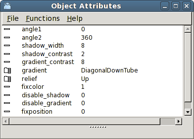
Fig Fixcolor is set on the frame
To be able to set dynamics we group the two circles. When we open the object editor for the
group the attribute DynType is available and we select DigLowColor. We set DigLowColor.Color
to a dark gray tone and connect DigLowColor.Attribute to a Dv, H1-Dv1.
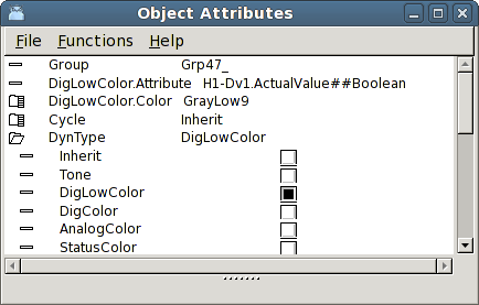
Fig Dynamic DigLowColor
The result is shown in the figure below. When the signal is high, the indicator is orange,
and when the signal is low, the indicator is dark gray.

Fig Indicator with low signal to the left and high to the right
The dynamic type DigColor is similar to DigLowColor, and it could also be used in this
example. The difference is that the function of the signal is inverted. In DigLowColor you
specify the color the object will get when the signal is low, while in DigColor you specify
the color the object will get when the signal is high.
Shift between several colors
We will now see how you can shift between several colors. We start with the indicator in the
example above and add the dynamic DigColor to DynType. In the object editor we now have the
attributes DigColor.Attribute and DigColor.Color. DigColor.Attribute is connected to a signal
in the database, H1-Dv2, and in DigColor.Color the color for high signal is stated. We insert
a blue color.
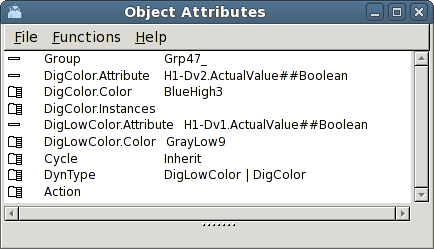
Fig A third color added with DigColor
The indicator will now shift between three different colors. DigLowColor shifts as before
between dark gray and orange dependent on H1-Dv1, and DigColor sets blue color when H1-Dv2
is hign. Note that DigColor has higher priority than DigLowColor. You can see this in the
object editor where the dynamics are ordered in priority order with highest priority at the
top and lowest priority at the bottom. The higher priority for DigColor implies that when
H1-Dv2 is high, the indicator is blue regardless of the value of H1-Dv1.

Fig The indicator is orange when H1-Dv1 is high and blue when H1-Dv2 is high
We will now add yet another color and study the Instance function. Some dynamic and action
types can occur in several copies, or several instances on the same object. For DigColor
this means that when we add yet another instance, you can set yet another color on the
object. As there are 32 instances available you can set 32 different colors, where each
color is connected to a signal in the database.
You add a DigColor instance by opening DigColor.Instance and mark instance 2. Now the
attributes for this instance are displayed, DigColor2.Attribute and DigColor2.Color. We
Connect DigColor2.Attribute to the signal H1-Dv3 and state a green color in DigColor2.Color.
Note that instances with higher instance number has higher prioriy, ie H1-Dv3 will color
the indicator green regardless of the value of H1-Dv1 and H1-Dv2.
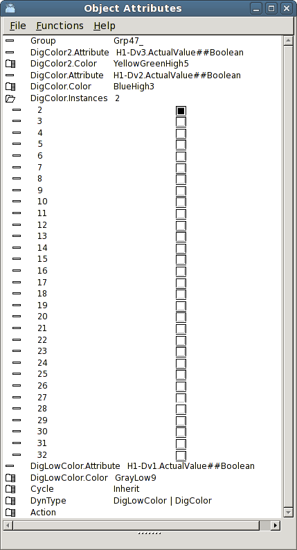
Fig A fourth color is added by DigColor instance 2
The result is displayed in the figure below. You can now shift between four different colors.
Beyond the three previous, dark gray, orange and blue, the indicator is now colored green when
H1-Dv3 is high.

Fig The indicator with four different colors
Colors for warning and error
In ProviewR the colors yellow and red are consistently used for warning and error respectively.
There are two types of dynamic, DigWarning and DigError, that sets yellow and red color.
The advantage compared to DigLowColor or DigColor is that you don't have to specify the color.
You just have to connect the dynamic to a digital signal in the database.
We use the indicator in the example above, and color it dark gray. This will be the color
when neither of the signals for DigWarning or DigError is high. We connect
DigWarning.Attribute to H1-Dv4 and DigError.Attribute to H1-Dv5.
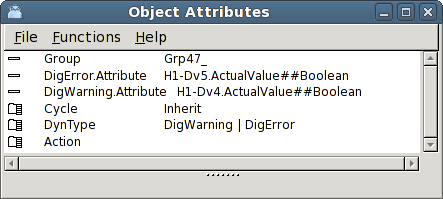
Fig Dynamic DigWarning and DigError
When no signal is set the indicator has the original color dark gray. When H1-Dv4 is set
it is colored yellow, and when H1-Dv5 is set it is colored red. DigError has higher
priority than DigWarning, thus it is red when H1-Dv5 is set, regardless of the value of
H1-Dv4.

Fig Yellow color for warning and red for error
Flashing dynamic
To get maximum attention to an object you can set DigFlash dynamic on it. DigFlash means
that the object will flash between two colors, when a signal is high. The flash rate equals
the scan time for the object. If Cycle is Slow, the flashing will be done with ScanTime for
the graph, and if Cycle is Fast with FastScanTime.
We set DigFlash dynamic to the indicator and can now state two colors that the object will
flash with, DigFlash.Color and DigFlash.Color2. We set DigFlash.Color to red and
DigFlash.Color2 to black, and connect DigFlash.Attribute to the signal H1-Dv6.
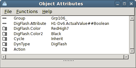
Fig DigFlash dynamic
When the signal H1-Dv6 is low the indicator has the original color dark gray. When H1-Dv6
is high it starts to flash with the colors red and black.

Fig The indicator flashes with red and black when the signal is high
Change the color of an analog signal
Now we will look at how to change the color of an object dependent on the value of an
analog signal. There are to different types of dynamic, FillColor and AnalogColor, that
are connected to analog signals. FillColor will color a portion of an object and to what
extent depends on the signal value. Analog color shifts the color of an object when the
signal value goes below or beyond a limit value.
Color up to a certain level
The dynamic FillColor colors an object up to a certain border line dependent on an analog
signal. It is similar to the bar object, with the difference that it can be applied to an
object of arbitrary shape. We will apply FillColor to a tank object fetched from
Hydraulics/Tank2 in the subgraph menu.
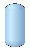
Fig A tank
The tank doesn't have any default dynamic. We mark FillColor in DynType and connect it to
the Av object H4-Av1. We also set a dark gray color in FillLevel.BackgroundColor.
FillLevel.MinValue and FillLevel.MaxValue specifies the range of the signal. The default
range is 0 - 100, implying that when the signal value is zero, the tank will be colored
with the background color, and when the value is 100, is is colored with the original blue
color we have set in the editor.
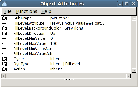
Fig Tank with FillColor dynamic
In the figure below H4-Av1 has the value 70 and the tank is filled to this level.
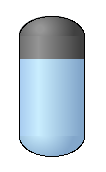
Fig The tank filled to a certain level
The tank can be filled in other directions by modifying FillColor.Direction. If the FillColor
dynamic is used in an object graph, also the range can be connected to attributes for min
and max values in the database.
Shift color beyond or below a certain limit
Often you want to display that an analog signal has gone beyond or below a certain value.
Suppose that in the tank example above, the level normally should be below 80, and if it
goes beyond 90 the situation is critical. We will use the dynamic AnalogColor to change the
color of the tank when the value passes the two limit values.
First we want to color the tank yellow when the signal H4-Av1 goes beyond 80. We add
AnalogColor to DynType and now we can set AnalogColor.Limit to 80. The type of limit value,
AnalogColor.LimitType is already GreaterThan, so we don't need to change it. We must though
specify the yellow color that will be set when the signal is greater than 80, and insert a
yellow tone in AnalogColor.Color.
To be able to add yet another limit value at 90, we add instance 2 in AnalogColor.Instances.
Now the attributes for AnalogColor2 appears and we set AnalogColor2.Limit to 90 and
AnalogColor2.Color to a red color. Note that you don't connect a new signal to instance 2,
but all instances uses the same signal.
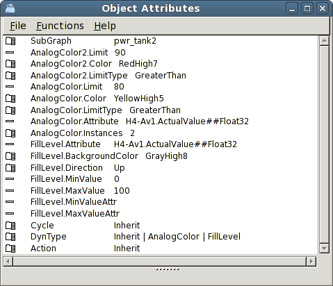
Fig AnalogColor dynamic
The result is viewed in the figure below. As long as the value of H4-Dv1 is less than 80 the
tank is blue. When the value is over 80, it's yellow, and when 90 is passed it's red.
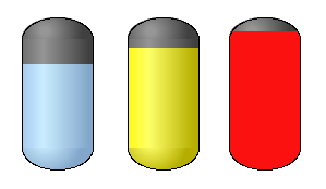
Fig At 80 the color is shifted to yellow, and at 90 to red
By setting LimitType to LessThan you can also add limit value for minimum levels, for example
color the tank yellow if the value is less than 20, and red if the value is less than 10.